Evaporator Blower
Objective
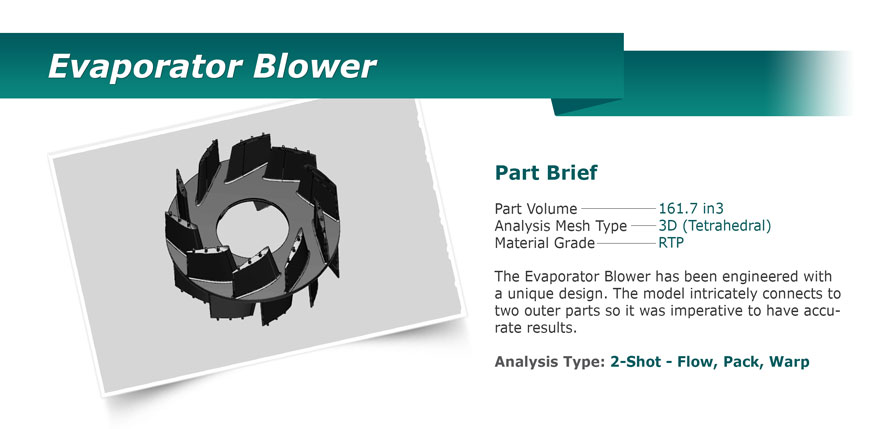
CAE Services was contracted to minimize the warpage in a three piece Evaporator Blower assembly. The evaporator blower was the most critical part of the assembly. This part presented two challenges. First, the part was complex with ten standing vanes per side and a molded-in aluminum insert. Second, the material was a 30% GF PP. Glass filled materials present the challenge of glass fiber alignment. Inadequate alignment can cause excessive warpage.

Flow / Pack Optimization
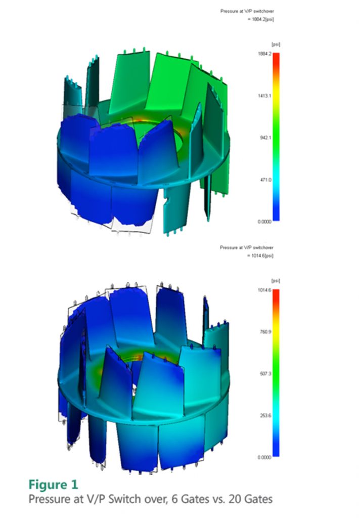
Initially, the tool shop planned to fill the Evaporator Blower with only six gates. This gate layout made for imbalanced filling with each vane filling out separately. The pressure imbalance caused poor volumetric shrinkage. CAE designed a twenty gate solution that filled each vane at the same time, subsequently lowering filling pressures (as shown in figure 1). This new design also optimized volumetric shrinkage uniformity which is important to ensure warpage (caused by differential shrinkage) would be minimized.
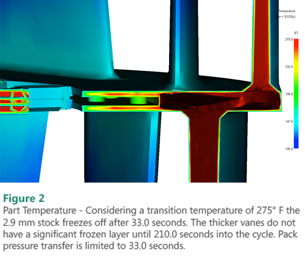
Despite optimizing the gate design for filling and packing, the vane features had high levels of shrinkage remaining at the base of the ribs. This was caused by a substantial amount of plastic at the base with 12.0 mm, verses a nominal wall of 2.9 mm. The 2.9 mm nominal that was used to gate into, froze off well before the thicker vanes did (figure 2). Therefore, pack pressure transfer was limited to that of the 2.9 mm wall stock. CAE recommended either reducing the thickness of the base or adding flow leaders from the gate to each vane to normalize the wall stock. This would help to equalize the frozen layers of both wall stocks so the vanes would be adequately packed.

Cooling Optimization
Once the gate design was optimized, the cooling design was incorporated into the analysis. CAE determined that the cooling circuits where sized efficiently to achieve turbulent flow at a reasonable circuit pressure. Also, the circuit placement was sufficient to achieve acceptable mold surface temperatures. The cycle time in this tool was limited by the thick vanes.Reducing the thickness of the vanes was the only way to decrease the cycle time without using a mold material with a higher thermal conductivity.
Summary
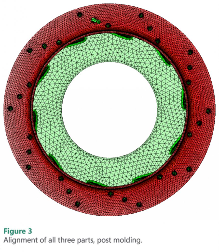
With the tool design and process settings dialed in, CAE Services engineers exported the predicted shape of the Evaporator Blower and assembled it to the two outer parts, the End Cap and the Inlet Orifice. A similar analysis was conducted on both of these tools (Figure 3). With all three parts optimized from mold construction to process settings, CAE Services determined that all three parts would mate successfully.

