

Co-Injection Analysis
Using specialized or layered part materials can lead to many issues for the finished part: unless you do a co-injection analysis first! Our co-injection simulation and analysis tests the process of injecting a skin material first, following by a different core material. Knowing the thickness of each part material is a crucial step to designing and molding the best part possible, saving time, money, and effort in the process.
CAE Co-Injection Analysis helps to determine:
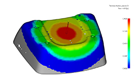
Thickness fraction of polymer B
shows what percentage of the wall is
occupied by the second polymer for
co-injection. This plot shows the
penetration about halfway
through the filling process.
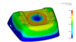
Thickness fraction of polymer B
shown at the end of injecting the
second polymer.
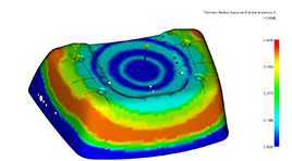
Thickness fraction of polymer B
shown at the end of injecting the
first polymer for the second time.
Consulting | Software | Training:
Improved Part Quality
Faster Cycle Times
Larger Processing Window
Less "Fire Fighting"
More Profit