
Moldflow was acquired by Autodesk in 2008. Autodesk has continued to improve the technology, but it did not start there. Let’s go back to the beginning. Moldflow started in Australia, in 1978, by Colin Austin. He worked at an injection molding machine manufacturer. And they wanted to predict the pressure that was required to fill the mold. Understandably, they wanted to recommend the right size machine, and predict the pressures that were required. In an interview with Colin, he was asked about his first line of code in Moldflow, he said it had to do with the cooling time calculation, which is interesting. What he did when writing code for Moldflow was use a strip file to create a description of the dominant flow path. He modeled thickness changes along that flow path and used the appropriate equations from thermodynamics and viscosities to be able to calculate that pressure. It was the use of the strip file that helped win me over when it came to using Moldflow analysis. Using strip files allowed us to come up with an initial process to run Moldflow analysis, that is now called molding window analysis.
It’s been 44 years since the start of Moldflow and the technology has evolved. It started with flow or filling studies, and over time added capabilities like packing, cooling, warpage analysis, and specialty processes as well. These Moldflow studies help determine part quality, warpage, and allow multiple iterations until you get to the solution. To predict the injection molding process, you need some inputs. You’ll need the mold design, the part will need to be represented with a mesh, material properties, and process conditions. I would argue that simulation expertise is important; because, you must know what’s happening with each input, and how to represent them properly in order to get solid answers out of Moldflow.
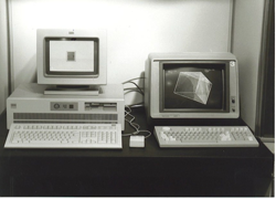
There has also been an evolution in solver technology for Moldflow. To get good answers from Moldflow the math behind it has to be pretty solid. As I mentioned, one of the inputs is representing your part using what we call a finite element mesh. In the early days we used a strip file, that’s the finite difference method. But finite element technology has evolved to spreading mesh out into more dimensions. Whereas the strip file was a one-dimensional input, the next step was doing a 2D lay flat. Imagine, a box representing a box, in just two dimensions. You would take the base and cut the box at the corners, laying the flaps of the box out flat onto a 2D plane. This method is easy enough for parts designed like a box; but how do you represent more complex geometry? Thankfully the technology evolved so that you could extend those 2D lay flats into 3 dimensions, but walls of a part was still a paper-thin wall with a thickness assigned to it. That’s the 2 1/2 D or mid plane and we still use that extensively today. From there it evolved into dual domain technology and full-blown 3D tetrahedral. So that’s describing the part and a lot of the math that goes behind it is built up into that finite element mesh.


Colin Austin worked at an injection machine manufacturer. He wanted to predict the pressure required to fill a mold. The 1st line of code was a cooling time calculation.
Material properties must be described as an input in Moldflow. In 1993 there was some 4,000 materials in the database, that has grown to 12,000 materials and the materials database continues to be more robust. It’s continually audited from release to release. We can designate which materials are fully characterized and which materials are partially characterized and what the implications of that are. Another input we need is process options. Initially it was all about fill time, and a melt temperature to mold temperature. Now you have a wide variety of process settings to control. The injection speed, for example, or the packing profiles, and any number of process setting you can dial in as a process option in Moldflow as well.
Finally, a few decades ago Moldflow Advisor technology became available. This put some of the power of Moldflow into the hands of product designers to help get a sense of whether or not their design is manufacturable.
Whether through solver technology, types of mech or input settings, Moldflow will continue to improve in order to increase the predictability of outcomes from mold simulation to the injection molding machine.
Consulting | Software | Training:
Improved Part Quality
Makes Customers Happy 🙂
Faster Cycle Times
Max Overall Equipment Effectiveness (OEE)
Larger Processing Window
Doesn't Require the "Wizard" to Set it Up
Less "Fire Fighting"
Means High Priority Projects Get Attention
More Profit
Boss Looks Great, We All Look Great!
Moldflow is like an MRI of your tool and the injection molding process. It has become one of the most influential technologies in the plastic injection molding industry over the last several decades. It is widely used throughout the industry. In this article you will find a brief history of Moldflow and the progress of solver technology and the inputs available for Moldflow studies.
Moldflow was acquired by Autodesk in 2008. Autodesk has continued to improve the technology, but it did not start there. Let’s go back to the beginning. Moldflow started in Australia, in 1978, by Colin Austin. He worked at an injection molding machine manufacturer. And they wanted to predict the pressure that was required to fill the mold. Understandably, they wanted to recommend the right size machine, and predict the pressures that were required. In an interview with Colin, he was asked about his first line of code in Moldflow, he said it had to do with the cooling time calculation, which is interesting. What he did when writing code for Moldflow was use a strip file to create a description of the dominant flow path. He modeled thickness changes along that flow path and used the appropriate equations from thermodynamics and viscosities to be able to calculate that pressure. It was the use of the strip file that helped win me over when it came to using Moldflow analysis. Using strip files allowed us to come up with an initial process to run Moldflow analysis, that is now called molding window analysis.
It’s been 44 years since the start of Moldflow and the technology has evolved. It started with flow or filling studies, and over time added capabilities like packing, cooling, warpage analysis, and specialty processes as well. These Moldflow studies help determine part quality, warpage, and allow multiple iterations until you get to the solution. To predict the injection molding process, you need some inputs. You’ll need the mold design, the part will need to be represented with a mesh, material properties, and process conditions. I would argue that simulation expertise is important; because, you must know what’s happening with each input, and how to represent them properly in order to get solid answers out of Moldflow.
There has also been an evolution in solver technology for Moldflow. To get good answers from Moldflow the math behind it has to be pretty solid. As I mentioned, one of the inputs is representing your part using what we call a finite element mesh. In the early days we used a strip file, that’s the finite difference method. But finite element technology has evolved to spreading mesh out into more dimensions. Whereas the strip file was a one-dimensional input, the next step was doing a 2D lay flat. Imagine, a box representing a box, in just two dimensions. You would take the base and cut the box at the corners, laying the flaps of the box out flat onto a 2D plane. This method is easy enough for parts designed like a box; but how do you represent more complex geometry? Thankfully the technology evolved so that you could extend those 2D lay flats into 3 dimensions, but walls of a part was still a paper-thin wall with a thickness assigned to it. That’s the 2 1/2 D or mid plane and we still use that extensively today. From there it evolved into dual domain technology and full-blown 3D tetrahedral. So that’s describing the part and a lot of the math that goes behind it is built up into that finite element mesh.
Colin Austin worked at an injection machine manufacturer. He wanted to predict the pressure required to fill a mold. The 1st line of code was a cooling time calculation.
Material properties must be described as an input in Moldflow. In 1993 there was some 4,000 materials in the database, that has grown to 12,000 materials and the materials database continues to be more robust. It’s continually audited from release to release. We can designate which materials are fully characterized and which materials are partially characterized and what the implications of that are. Another input we need is process options. Initially it was all about fill time, and a melt temperature to mold temperature. Now you have a wide variety of process settings to control. The injection speed, for example, or the packing profiles, and any number of process setting you can dial in as a process option in Moldflow as well.
Finally, a few decades ago Moldflow Advisor technology became available. This put some of the power of Moldflow into the hands of product designers to help get a sense of whether or not their design is manufacturable. Whether through solver technology, types of mech or input settings, Moldflow will continue to improve in order to increase the predictability of outcomes from mold simulation to the injection molding machine.
Consulting | Software | Training:
Improved Part QualityMakes Customers Happy :)Faster Cycle TimesMax Overall Equipment Effectiveness (OEE)Larger Processing WindowDoesn’t Require the “Wizard” to Set it UpLess “Fire Fighting”Means High Priority Projects Get AttentionMore ProfitBoss Looks Great, We All Look Great!
Company*Name*
First
Last
Email*
Phone*Comments*CAPTCHA
jQuery(document).ready(function($){gformInitSpinner( 2, ‘https://caeservices.com/wp-content/plugins/gravityforms/images/spinner.gif’ );jQuery(‘#gform_ajax_frame_2’).on(‘load’,function(){var contents = jQuery(this).contents().find(‘*’).html();var is_postback = contents.indexOf(‘GF_AJAX_POSTBACK’) >= 0;if(!is_postback){return;}var form_content = jQuery(this).contents().find(‘#gform_wrapper_2’);var is_confirmation = jQuery(this).contents().find(‘#gform_confirmation_wrapper_2’).length > 0;var is_redirect = contents.indexOf(‘gformRedirect(){‘) >= 0;var is_form = form_content.length > 0 && ! is_redirect && ! is_confirmation;var mt = parseInt(jQuery(‘html’).css(‘margin-top’), 10) + parseInt(jQuery(‘body’).css(‘margin-top’), 10) + 100;if(is_form){jQuery(‘#gform_wrapper_2’).html(form_content.html());if(form_content.hasClass(‘gform_validation_error’)){jQuery(‘#gform_wrapper_2’).addClass(‘gform_validation_error’);} else {jQuery(‘#gform_wrapper_2’).removeClass(‘gform_validation_error’);}setTimeout( function() { /* delay the scroll by 50 milliseconds to fix a bug in chrome */ jQuery(document).scrollTop(jQuery(‘#gform_wrapper_2’).offset().top – mt); }, 50 );if(window[‘gformInitDatepicker’]) {gformInitDatepicker();}if(window[‘gformInitPriceFields’]) {gformInitPriceFields();}var current_page = jQuery(‘#gform_source_page_number_2’).val();gformInitSpinner( 2, ‘https://caeservices.com/wp-content/plugins/gravityforms/images/spinner.gif’ );jQuery(document).trigger(‘gform_page_loaded’, [2, current_page]);window[‘gf_submitting_2’] = false;}else if(!is_redirect){var confirmation_content = jQuery(this).contents().find(‘.GF_AJAX_POSTBACK’).html();if(!confirmation_content){confirmation_content = contents;}setTimeout(function(){jQuery(‘#gform_wrapper_2’).replaceWith(confirmation_content);jQuery(document).scrollTop(jQuery(‘#gf_2’).offset().top – mt);jQuery(document).trigger(‘gform_confirmation_loaded’, [2]);window[‘gf_submitting_2’] = false;}, 50);}else{jQuery(‘#gform_2’).append(contents);if(window[‘gformRedirect’]) {gformRedirect();}}jQuery(document).trigger(‘gform_post_render’, [2, current_page]);} );} ); jQuery(document).bind(‘gform_post_render’, function(event, formId, currentPage){if(formId == 2) {if(typeof Placeholders != ‘undefined’){
Placeholders.enable();
}jQuery(‘#input_2_4’).mask(‘(999) 999-9999’).bind(‘keypress’, function(e){if(e.which == 13){jQuery(this).blur();} } );} } );jQuery(document).bind(‘gform_post_conditional_logic’, function(event, formId, fields, isInit){} ); jQuery(document).ready(function(){jQuery(document).trigger(‘gform_post_render’, [2, 1]) } );