
Ask The Moldflow Experts
Appearance Issues in Moldflow
Ask The Moldflow Experts Webinar Topic:
Appearance Issues in Moldflow
November 30th, 2021 | 12:30 PM CDT
One of the most time-consuming and frustrating things about injection molding can be chasing appearance issues after all of the efforts that go into engineering the part and mold. Join our webinar to see how CAE Services’ Experts solve appearance problems and plan to avoid them in the first place.
- Learn different approaches to solving/avoiding knit lines in your part;
- Learn how part design and gate locations can affect the formation of air traps;
- Learn how to size gates properly to avoid gate blush;
- Discover the causes of sink marks and how to avoid them;
- In-depth topic discussion with questions fielded during the presentation + Q&A at the end of the webinar

ATME - Take Away


Knit Lines
The Problem
-
Blemish that occurs from the collision of two flow fronts
-
Reduces strength
-
Unsightly appearance
-
Often unavoidable due to geometry features
-
Holes
-
Tall standing cores
-
The Solution
-
Parts with holes will have knit lines
-
Mold part with hole filled and punch/machine the hole
-
Place knit line in acceptable area
-
-
Move gate?
-
If you’re lucky
-
-
Re-sequence the flow
-
If you have valve gates
-
-
Modify the part design
-
Flow leaders/restrictors
-
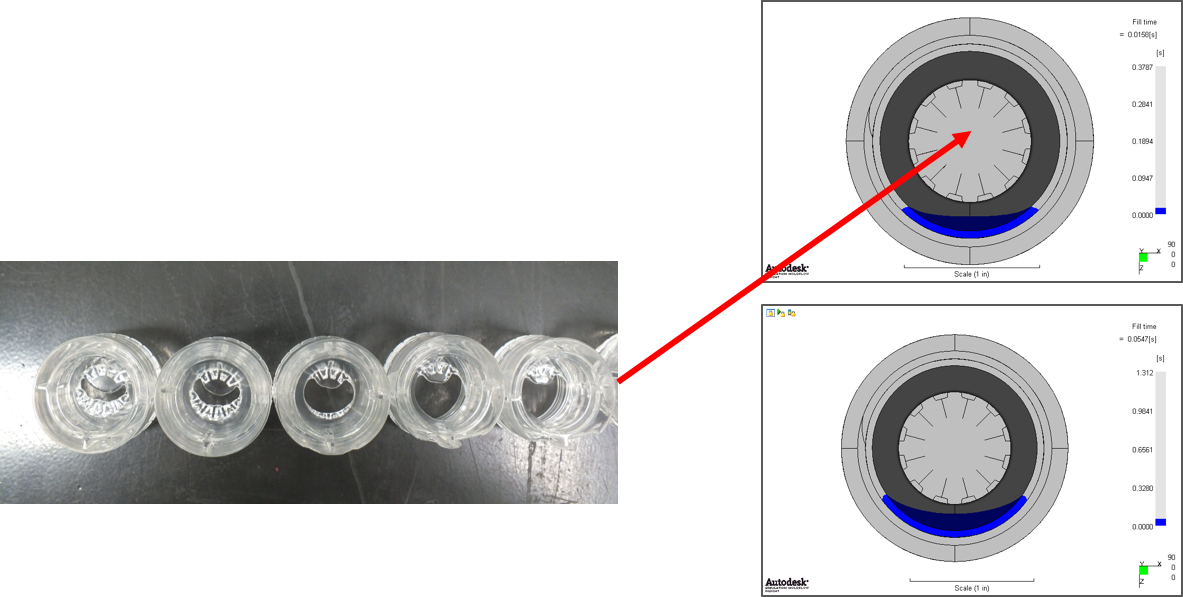
Air Traps
The Problem
-
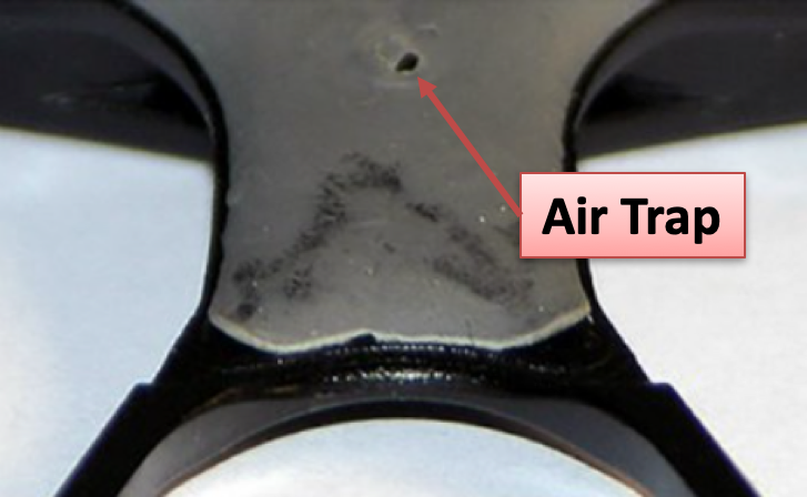
Air that occupies the mold must get out as plastic flows
-
Supposed to be through vents
-
Part design/gate position can produce backfilling/racetracking
-
Non-fills or burned material
-
Compressed air pushes back on melt front
-
Compressed air = temp increase
-
The Solution
Existing tool - Faster filling
Existing tool - vacuum venting
Existing tool - Part Design Change
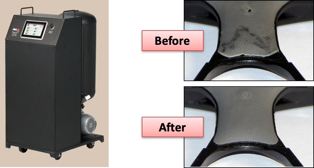
-
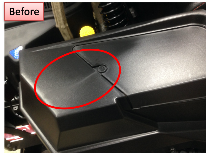
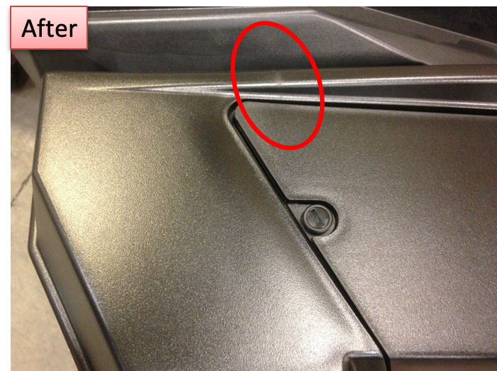
Air trap in optical area was unacceptable
-
Increased wall thickness in optical area
-
Air trap moved to acceptable area
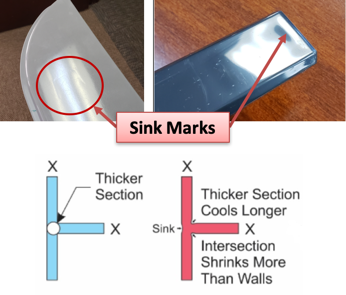
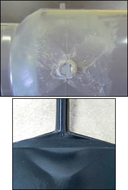
Sink Marks
The Problem
-
Depression at the surface where back side features intersect
-
Sometimes in very thick sections
-
Caused by excessive shrinkage
-
Thicker section
-
Farther from gate
-
Higher temp
-
Higher shrink materials
-
Beware of corners!
-
The Solution
Existing tool - improving sink
-
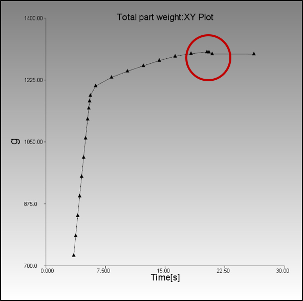
Do a gate freeze study
-
Reduce rib/wall ratio
-
Welding involved
-
-
Increase pack pressure
-
Increases clamp force requirement
-
-
Move gate(s)
-
May not be possible
-
May cause unintended consequences
-
new tool - use simulation results
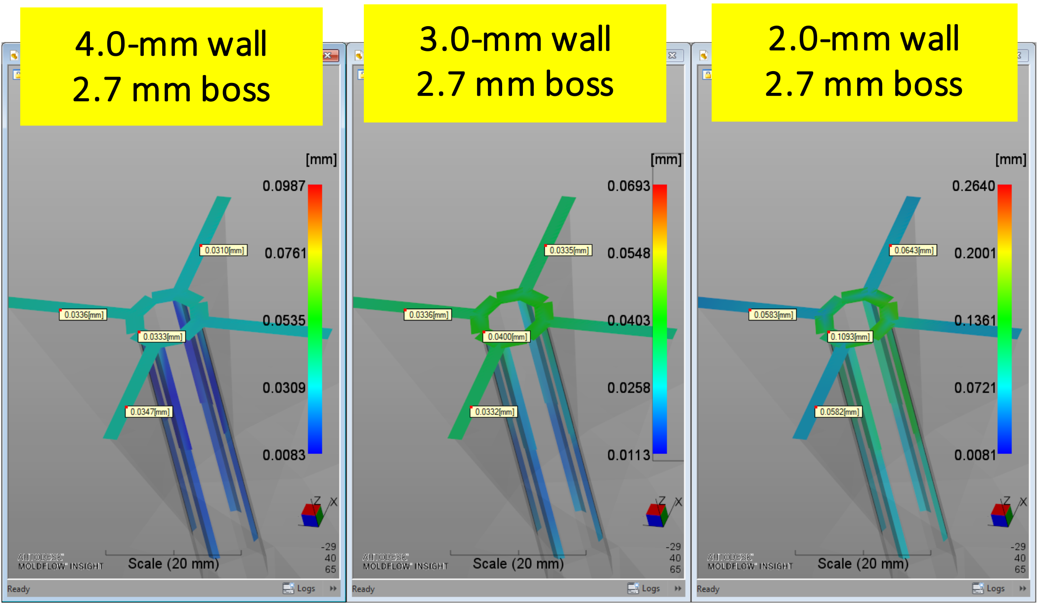
-
Reduce rib/wall ratio
-
No welding involved
-
Use sink savers?
-
Beware of short shots
-
-
Move gate(s)
-
Closer to areas of sink
-
-
Sink Depth Results
-
Keep below 0.1 mm
-
Below 0.025 mm for glossy finishes
-
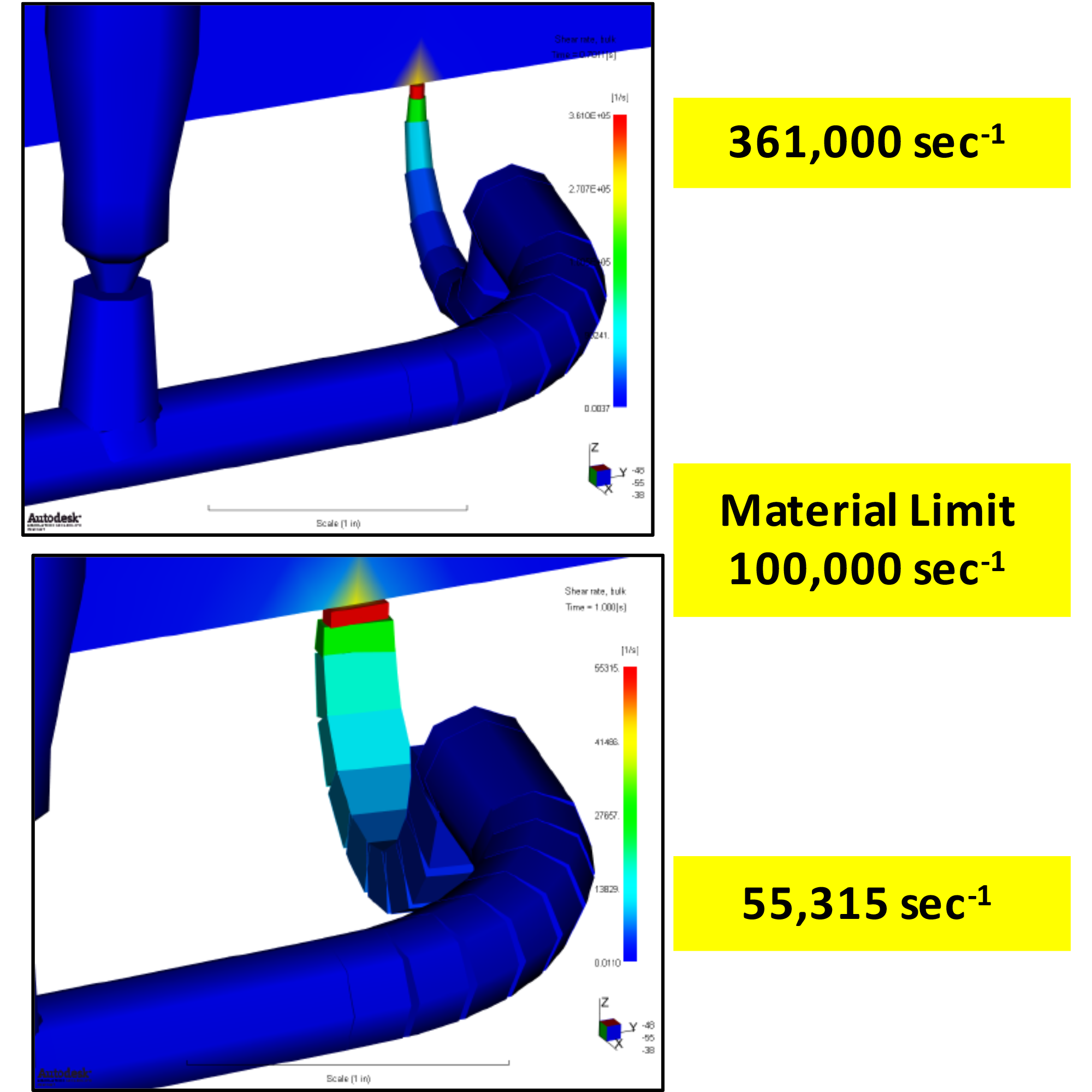
Blush
The Problem
gate blush
-
Blemish extending from the gate
-
Caused by material degradation
-
Excessive shearing breaks molecular chains
-
Thin gates
-
Too few gates
-
Fill rate too fast
-
The Solution
Existing tool - improving gate blush
-
Slow down fill speed
-
May cause unintended consequences
-
-
Increase gate size
-
May be undesirable
-
May cause sink near gate area
-
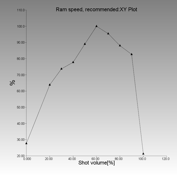
new tool - use simulation results
-
Ensure proper number of gates
-
Increase gate size
-
Use ram-speed profiling
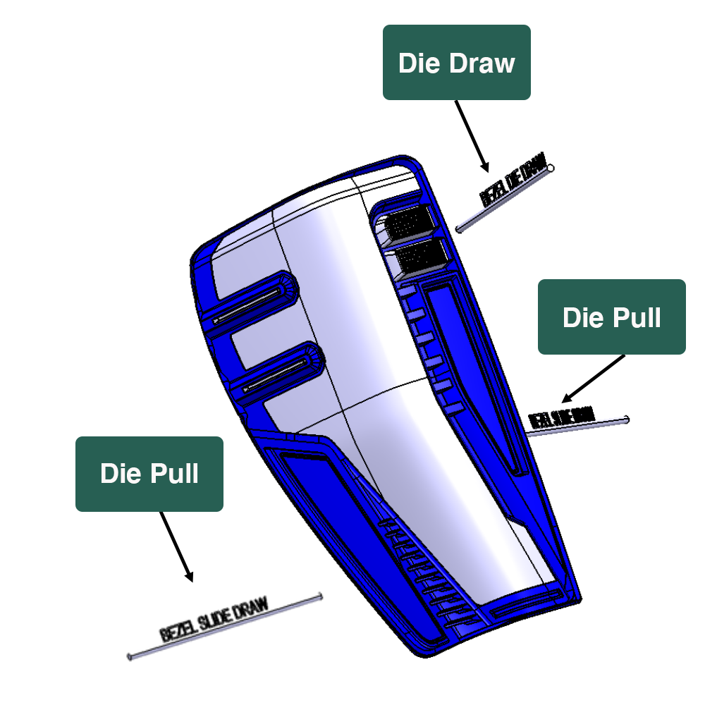
Make sure part is "feased"
-
Preliminary Feasibility Study Assures:
-
Part is good for tooling
-
Sufficient side wall draft
-
Rib-to-wall ratio
-
Proper fit/function
-
Basic die draw, die pull directions identified
-
Some Parting Thoughts
-
Use simulation upfront before mold is built
-
Try to hardwire solutions into part or mold design
-
Use Expert Moldflow engineers
-
Expertise helps us know when results are reasonable
-
Material Data
-
Mesh
-
Know how to:
-
Identify causes
-
Solve Problems
-
Mold/Part Design
-
Process to fix aesthetics
-
-
-

Appearance Issues in Moldflow
Ask The Moldflow Experts Webinar Topic:
Appearance Issues in Moldflow
November 30th, 2021 | 12:30 PM CDT
One of the most time-consuming and frustrating things about injection molding can be chasing appearance issues after all of the efforts that go into engineering the part and mold. Join our webinar to see how CAE Services’ Experts solve appearance problems and plan to avoid them in the first place.
Learn different approaches to solving/avoiding knit lines in your part;
Learn how part design and gate locations can affect the formation of air traps;
Learn how to size gates properly to avoid gate blush;
Discover the causes of sink marks and how to avoid them;
In-depth topic discussion with questions fielded during the presentation + Q&A at the end of the webinar
ATME – Take Away
If you are experiencing appearance issues:
Email Us Today!
#id-4011 .carousel-slider-nav-icon {
fill: #f1f1f1
}
#id-4011 .carousel-slider-nav-icon:hover {
fill: #00d1b2
}
#id-4011 .owl-prev,
#id-4011 .owl-next,
#id-4011 .carousel-slider-nav-icon {
height: 48px;
width: 48px
}
#id-4011.arrows-outside .owl-prev {
left: -48px
}
#id-4011.arrows-outside .owl-next {
right: -48px
}
#id-4011 .owl-dots .owl-dot span {
background-color: #f1f1f1;
width: 10px;
height: 10px;
}
#id-4011 .owl-dots .owl-dot.active span,
#id-4011 .owl-dots .owl-dot:hover span {
background-color: #00d1b2
}
Knit Lines
The Problem
Blemish that occurs from the collision of two flow fronts
Reduces strength
Unsightly appearance
Often unavoidable due to geometry features
Holes
Tall standing cores
The Solution
Parts with holes will have knit lines
Mold part with hole filled and punch/machine the hole
Place knit line in acceptable area
Move gate?
If you’re lucky
Re-sequence the flow
If you have valve gates
Modify the part design
Flow leaders/restrictors
Air Traps
The Problem
Air that occupies the mold must get out as plastic flows
Supposed to be through vents
Part design/gate position can produce backfilling/racetracking
Non-fills or burned material
Compressed air pushes back on melt front
Compressed air = temp increase
The Solution
Existing tool – Faster filling
Existing tool – vacuum venting
Existing tool – Part Design Change
Air trap in optical area was unacceptable
Increased wall thickness in optical area
Air trap moved to acceptable area
Sink Marks
The Problem
Depression at the surface where back side features intersect
Sometimes in very thick sections
Caused by excessive shrinkage
Thicker section
Farther from gate
Higher temp
Higher shrink materials
Beware of corners!
The Solution
Existing tool – improving sink
Do a gate freeze study
Reduce rib/wall ratio
Welding involved
Increase pack pressure
Increases clamp force requirement
Move gate(s)
May not be possible
May cause unintended consequences
new tool – use simulation results
Reduce rib/wall ratio
No welding involved
Use sink savers?
Beware of short shots
Move gate(s)
Closer to areas of sink
Sink Depth Results
Keep below 0.1 mm
Below 0.025 mm for glossy finishes
Blush
The Problem
gate blush
Blemish extending from the gate
Caused by material degradation
Excessive shearing breaks molecular chains
Thin gates
Too few gates
Fill rate too fast
The Solution
Existing tool – improving gate blush
Slow down fill speed
May cause unintended consequences
Increase gate size
May be undesirable
May cause sink near gate area
new tool – use simulation results
Ensure proper number of gates
Increase gate size
Use ram-speed profiling
Make sure part is “feased”
Preliminary Feasibility Study Assures:
Part is good for tooling
Sufficient side wall draft
Rib-to-wall ratio
Proper fit/function
Basic die draw, die pull directions identified
Some Parting Thoughts
Use simulation upfront before mold is built
Try to hardwire solutions into part or mold design
Use Expert Moldflow engineers
Expertise helps us know when results are reasonable
Material Data
Mesh
Know how to:
Identify causes
Solve Problems
Mold/Part Design
Process to fix aesthetics